To build a traffic light circuit using switches, LEDs, and a 555 timer IC, follow these steps:
Components Required:
- 555 Timer IC
- LEDs (Red, Yellow, Green)
- Resistors (330Ω for LEDs, other values for timer)
- Capacitors (based on timing requirement)
- SPDT switches or push buttons
- Breadboard or PCB
- Connecting wires
- 9V battery or 5V power supply
- Transistors (if necessary for driving LEDs)
Circuit Design:
- 555 Timer Configuration:
The 555 timer IC will be configured in astable mode to generate a continuous pulse. This pulse will control the time duration for the red, yellow, and green LEDs to light up sequentially. Astable Mode Formula:
[
T = 0.693 \times (R_1 + 2R_2) \times C
]
Where:
- (T) is the total period
- (R_1) and (R_2) are resistors
- (C) is the capacitor Set appropriate values of (R_1), (R_2), and (C) to achieve the desired timings for each light.
- LEDs:
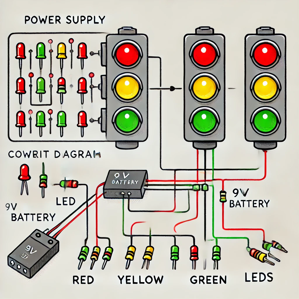
- Connect Red, Yellow, and Green LEDs to the output of the 555 timer IC via 330Ω resistors to limit current.
- The LEDs will light up sequentially depending on the pulse generated by the timer.
- Switches:
Use SPDT switches to manually change the state of the lights. The switches can be used to simulate a pedestrian crossing or traffic light change. - Timing:
- The 555 timer will output a continuous square wave signal. By adjusting the values of resistors and capacitors in the timer circuit, the time intervals for the red, yellow, and green lights can be controlled. Typically, the green light stays on longer than the yellow and red lights.
- Power Supply:
Provide power to the circuit using a 9V battery or a regulated 5V power supply.
Circuit Explanation:
- The 555 timer will output a continuous pulse that will drive the LEDs in sequence.
- The first LED (red) will turn on, followed by the yellow LED, then the green LED.
- By adjusting the resistors and capacitors, you can change how long each LED stays lit.
- Switches can be added to override the sequence, simulating a manual traffic control mechanism.
Circuit Diagram:
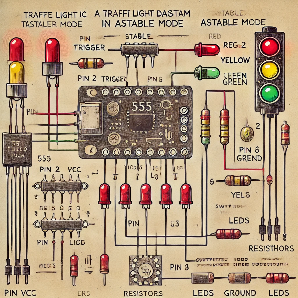
- The 555 timer will have pins connected as follows:
- Pin 1: Ground
- Pin 2: Trigger (connected to pin 6)
- Pin 3: Output (to LEDs)
- Pin 4: Reset (tied to Vcc)
- Pin 5: Control Voltage (optional, tie to ground via capacitor)
- Pin 6: Threshold (connected to pin 2 via resistor)
- Pin 7: Discharge (connected to pin 6 via resistor)
- Pin 8: Vcc (connected to power supply)
- 555 Timer Configuration:
- Pin 1 to Ground.
- Pin 2 and Pin 6 are connected together.
- Pin 4 and Pin 8 connected to Vcc.
- Pin 3 (output) connects to the LEDs (with resistors in series).
- Use two resistors and one capacitor to control timing between Pin 6, Pin 7, and Pin 2.
- LED and Resistor Wiring:
- Connect the Red LED (with a 330Ω resistor) to Pin 3.
- Use additional transistors if you plan to power high-power LEDs.
Notes:
- You can use multiple 555 timers for more complex timing configurations or to control multiple lights with precise timings.
- Transistors may be needed if you’re using high-power LEDs or want to drive multiple LEDs from the same pin.
Example Timing Configuration:
- Set R1 = 1kΩ, R2 = 5kΩ, and C = 100µF for example timing. Adjust values to set the time for each light to be on.
Simplified Traffic Light Timing:
- Red LED: ON for 5 seconds.
- Yellow LED: ON for 2 seconds.
- Green LED: ON for 5 seconds.
Use two more 555 timers (or a counter IC like 4017 decade counter) for more accurate sequential control of the lights.

